This is Part 7 of an eight-part series describing how to design a database for a Workflow Engine. Check out Part 1 here:
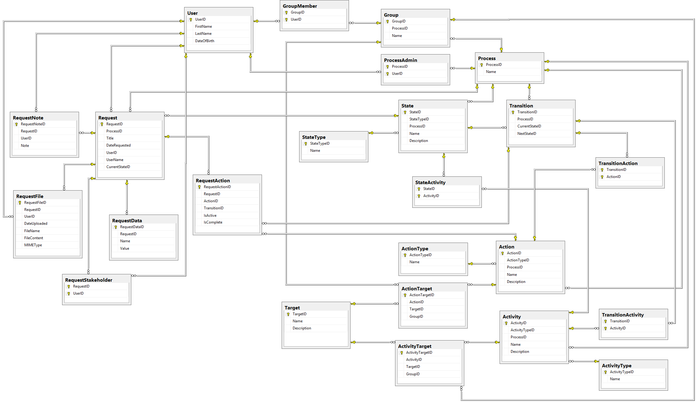
All of the infrastructure we've built so far has lead to this moment. At long last, we can build the final piece of our schema: the Request Actions table.
Request Actions
So we now have Actions that Users can perform to invoke Transitions. Obviously we can't allow for any action to be performed against the Request; only the actions we need should be allowed.
The Table
Let's look at the schema of the RequestActions table first, and then show how it would actually be used:
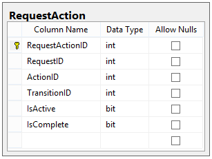
Those last two columns (IsActive and IsComplete) are very important to the actual execution of this table.
Here's how we're going to use this table.
- When a Request enters a State, we get all outgoing Transitions from that state. For each Action in those Transitions, we add an entry in RequestAction, with each entry having IsActive = 1 and IsCompleted = 0.
- A User may submit an Action at any time. Each submitted Action consists of an ActionType, a RequestID, and a UserID.
- When an Action is submitted, we check the RequestActions for the specified Request. If the submitted Action matches one of the active RequestActions (where IsActive = 1), we set that entry's IsActive = 0 and IsCompleted = 1.
- After marking the submitted Action as completed, we check all Actions for that Transition in that Request. If all RequestActions are marked as Completed, then we disable all remaining actions (by setting IsActive = 0, e.g. all actions for Transitions that were not matched).
Sample Walkthrough
Let's see if we can see how this works by introducing some sample data.
USERS: Jane (ID 1), Tom (ID 2), Gary (ID 3)
GROUPS: Executives (ID 1), includes Tom and Gary
STATES: A (Type: Start), B (Type: Normal), C (Type: Denied)
TRANSITIONS: A -> B (ID 1), A -> C (ID 2), B -> C (ID 3)
TRANSITION ACTIONS:
A -> B: Approved by Requester (ID 1) AND Approved by Executives (ID 2)
A -> C: Denied by Executives (ID 3)
B -> C: Denied by Requester (ID 4)
Let's say Jane creates a Request, which immediately is placed into State A.
At this point, the system looks for all outgoing transitions from State A and finds two of them, Transitions 1 and 2. It then loads the following data into RequestActions:
| RequestID | ActionID | TransitionID | IsActive | IsComplete |
|---|---|---|---|---|
| 1 | 1 | 1 | YES | NO |
| 1 | 2 | 1 | YES | NO |
| 1 | 3 | 2 | YES | NO |
Now the Request just sits in its current state, waiting for an Action to be submitted.
Say Jane submits this action:
ACTION:
User ID: 1
ActionType: Approve
Request ID: 1
(We read that as "User 1 approves Request 1")
Since that action matches the first RequestAction in the table, it is marked as completed:
| RequestID | ActionID | TransitionID | IsActive | IsComplete |
|---|---|---|---|---|
| 1 | 1 | 1 | NO | YES |
| 1 | 2 | 1 | YES | NO |
| 1 | 3 | 2 | YES | NO |
At this point, we have not matched all Actions for a Transition, so nothing happens to the Request; it remains in State A.
Now say Tom submits this action:
ACTION:
User ID: 2
ActionType: Approve
Request ID: 1
(User 2 approves Request 1)
After that action gets matched, the table of Request Actions now looks like this:
| RequestID | ActionID | TransitionID | IsActive | IsComplete |
|---|---|---|---|---|
| 1 | 1 | 1 | NO | YES |
| 1 | 2 | 1 | NO | YES |
| 1 | 3 | 2 | YES | NO |
Notice that because both Actions for Transition 1 are complete, we now must follow Transition 1 and move the Request to the next State, which is State B. After we move to State B, we load the Actions for the Transitions from that State and disable any old Actions; our RequestActions table looks like this:
| RequestID | ActionID | TransitionID | IsActive | IsComplete |
|---|---|---|---|---|
| 1 | 1 | 1 | NO | YES |
| 1 | 2 | 1 | NO | YES |
| 1 | 3 | 2 | NO | NO |
| 1 | 4 | 3 | YES | NO |
In this manner, we can keep track of all actions that have been performed, that could have been performed, and that are still waiting to be performed, in the same table.
What did we accomplish?
In this post, we implemented the last piece of our structure: the Request Actions table. This table stores all Actions that can be made against a particular Request, and is the driving force behind how this engine actually works.
There's still one last part we will talk about, and that's actually building and demoing a process that runs on this engine.
The final part of our saga is Part 8, where we will discuss the complete schema and shortcomings of the design of our Workflow Engine database.
Happy Coding!
